Ahhh...the clean air, the peacefulness, and now retired in Skyforest. Retirement gives us the time for projects, such as restoring a vintage Shopsmith, remodeling our log home, or perhaps just dealing with what mother nature doles out while living at 6,000 feet. Welcome to the Skyforest Life.

Monday, December 10, 2012

Shopsmith Episode 9: “...Halfway to Paradise” - A Mid-Term Progress Report


I am a little over half way through the Shopsmith “Rusty” restoration project.  What has been the progress so far?  What’s remaining?  What would a Progress Report Card look like?  We address these issues and more in this mid-term episode.

Status

A little over three months have gone by since the harrowing recovery and extraction of Rusty in late August.  Some before pictures:


Over the past three months, the progress & activities include:
  • Cleaned & painted the bench ends
  • Built a new redwood platform
  • Added new casters
  • Cleaned the headstock & rebuilt the quill assembly
  • Cleaned the baseplate, baseplate arm, carriage, headrest, tie bar, and tubular ways.
  • Cleaned and rebuilt the speed changer
  • Cleaned and rebuilt the Jacob’s Chuck
  • Tested the motor
  • Maintained a blog intertwined with cheap jokes and puns


Progress Photos to date:


OK - so far so good I suppose....but what might my report card look like?


Well, I’m glad my parents don’t have to read and sign the report card!


For those of you who may missed the first eight episodes, or simply can’t get enough of this blog and need more, here is a one-sentence synopsis of the progress and activites so far:

Episode 1: Late August - conduct Recon of Shopsmith in disgusting garage near high desert of California (hum theme song to Indiana Jones), return with reinforcements to extract Shopsmith & relocate to safe house in Skyforest, CA (hum theme song to Mission Impossible); Episode 2: a Shopsmith 101 tutorial (*yawn*); Episode 3:  Clean up Way Tubes (can you say Evapo-Rust?); Episode 4: Clean Headstock & rebuild quill assembly  (whew - spring still works); Episode 5:  Fire-up the motor (still can’t get out of the haz-mat suit); Episode 6: Clean up baseplate, tie bar, and other boring pieces; Episode 7:  Repaint bench ends & build new redwood platform (lookin’ good!); Episode 8: Clean & Rebuild speed changer (Can you calculate the final speed?).


Remaining Restoration Projects:

So what’s left to do?  The remaining restoration tasks include:

  • Clean motor & bracket, & remount onto the Shopsmith
  • Decide whether to repaint the motor and belt guard..or clean and leave as-is.
  • Buy belts and align/adjust the drive train
  • Pray that the bearings don’t need to be replace
  • Fire up that sucker and see what happens
  • Clean & rebuild the table
  • Clean the Tailstock & tool rest
  • Clean sanding disk & find sand paper which will fit
  • Clean fence and table extension
  • Clean and rebuild the 4” jointer
  • Figure out what to do with a 4” jointer
  • Look for something to build once it is all together
  • Maintain the blog site with clever updates and maybe more expensive jokes

See you on the next blog update.

Sunday, November 25, 2012

Shopsmith Episode 8: I feel the Need...the Need for Speed!


This episode is a two-fer:  The first part will explore changing speeds on the Shopsmith and the restoration of the Shopsmith Speed Changer.  

The second special bonus part is a reader challenge to see how well you paid attention in high school math classes.  

This episode is all about speed - but not simply about having more speed, but about the ability to vary the speed.  There are many examples of methods of varying speed.   This old hand crank drill is easy to adjust the speed...just crank faster.  There is the option today of adding a variable speed motor to the Shopsmith.


The steam locomotive ran on, well, steam.  A throttle is used to regulate the amount of steam to the piston/cylinder hence increasing or decreasing the power to the locomotive drive train.  Yet even with this capability, Dr. Emmett Brown invented green, yellow, and red presto logs in order to sequentially increase the speed of the locomotive to reach 88 miles per hour, enabling the Delorean to enter temporal displacement (Great Scott!).  

However, the Shopsmith has no use for presto logs...at least at the moment.


Ten speed bicycles use a series of gears/sprockets to adjust the speed of the bike.  To change speeds, you change the chain to a different sprocket through the use of a Derailleur.


Similar to the bicycle, the early Shopsmith included the ability to adjust its speed using a belt driving multiple size pulleys.  To change speeds, you changed the belt to a different pulley combination.  For example, Belt position “3” increases the speed of the Headstock spindle (the motor pulley is large than the headstock pulley), while belt position “1”slows the headstock speed  (the motor pulley is smaller than the headstock pulley).  


To change the headstock speed, you loosen the motor brackets, and relocate the belt to a different pulley, and reposition the motor.  This is like changing gears on your bicycle by stopping your bike, removing the rear wheel, manually moving the chain to a different sprocket, then reassembling the wheel, and resuming your bike ride.  

Doable, but not very efficient...and not very much fun.


The Speed Changer


The people at Magna Engineering invented one of the most clever devices I have ever seen, called the Speed Changer (the cleverness is in the design...not the name).  The SC mounts on the Way Tubes between the motor and the Headstock pulleys.  Two belts are used:  one from the motor to drive the SC pulleys, and a second belt from the SC to drive the headstock pulley.  The knob on the right turns which raises or lowers the center pulley assembly, and thereby adjusting the speed of the headstock.


Unfortunately, Rusty’s Speed Changer doesn’t slide on the Way tubes, doesn’t raise or lower, and doesn’t rotate around its own shaft with much enthusiasm.  


After removing Rusty’s Speed Changer assembly and with some soaking, cleaning, polishing, and some waxing, the pulleys now spin about their shaft (with much more enthusiasm), the knob rotates nicely moving the pulley assembly up and down, and the entire assembly slides on the Way Tubes.  I reinstalled the Speed Changer, and began dreaming about the next step: which will be the motor and its mounting bracket.  Then alignment of all the parts, add the belts, and complete the drive train.


Later that evening.... 

Lying in bed around 3:00 in the morning, relishing in my accomplishment of getting the Speed Changer restored without much bother, it began to gnaw at me that just moving the pulleys up and down doesn’t necessarily change the speed of the spindle.  All it would do is make one belt tighter, and there other one looser.  SOMETHING'S NOT RIGHT!

Later that same day.... 

I re-read the Speed Changer Set-up paper (provided by MICKYD of the Shopsmith10ER Users Group) as well as other user forums on the Speed Changer, and sure ‘nuf: their’s more.  The middle part of the SC pulley system is also supposed to slide back and forth (hence the term “floating sheave”).  This is where the cleverness comes in (about the Speed Changer...not me).

As the SC pulley system is raised or lowered, the floating sheave slides to the right or left allowing the belts to come closer to or farther away from the center part of the SC in perfect harmony.  This has the effect of increasing or decreasing the radius of the belts around the center pulleys, and hence adjusting the speed of the headstock spindle. 

Clever, no?


I went out to the shop to check on Rusty’s Speed Changer to see if the center part slides back and forth....nope.  Remove the SC, back on the shop table, and proceed to disassemble the center pulley system.  Unfortunately, I could find no set of instructions on any forum group which would help at this level...so I am on my own.  The outer sheaves have set screws, which I removed, but still nothing moves.  Everything is frozen onto the center shaft (after 20 - 30 years of no use). 

Using a gear puller, WD40 to help loosen the parts, and a few choice words of encouragement (or were they threats?), I was able to finally get all three sheaves disassembled from the center shaft.

And it is no wonder that the floating sheave doesn’t float.  There is a ton of anti-floating rust and corrosion everywhere.  


More cleaning, polishing, and viola!...the center sheave floats like a butterfly. 


Mount it back onto Rusty.   NOW I am ready for the motor and its mounting bracket, then finally new belts and alignment.


READERS CHALLENGE:

For no extra charge, a second bonus part has been added to this blog episode which, to be honest, requires the use of basic algebra and geometry which we all slept through studied in high school.  I know, you thought when you were taking this stuff in high school, that you would never really use it in real life.  Well here’s your chance!  And you can tell your grandkids that you actually had to use this in real life, and to pay attention in school. 

Good Luck!

The challenge: The drive train on the Shopsmith is set up with four pulleys:  One on the motor, one on the speed changer driven from the motor pulley, a second on the speed changer which drives the headstock spindle, and finally the headstock spindle.  Given the diameters and radius of all four pulleys (see diagram), and the speed of the motor at 3600 rpm, can you calculate the speed of the headstock spindle?


Hint: It is based on the ratios of the circumferences of the pulleys.  

This will be open book...but please do your own work.  And no fair peeking at the section which follows.  Good Luck!


To begin:  the basics. For every complete rotation of the motor, the motor pulley drives the belt so many inches based on its circumference.  To determine the speed of the second pulley, we divide the circumference of the motor pulley by the circumference of the second pulley (to determine how many rotations there will be of the second pulley for every one rotation of the first pulley).  We then multiply that ratio times the speed of the motor to obtain the speed of the second pulley.


If you remember from your geometry class, the circumference is equal to 2 times Pi times the radius.  Since we are dividing one circumference by the other circumference, we needn’t care about the "2"and Pi...they cancel themselves out.


So let’s start by determining the speed of the speed changer.  The motor pulley has a diameter of 2”, which gives us a radius of 1”.  The diameter of the speed changer pulley being driven by the motor is 1.75” giving us a radius of 0.875”.  The motor is running at 3600 rpm.  We divide 1” by 0.875”, and multiply that by 3600 to get a speed changer speed of 4114 rpm.  A slight speed increase.


The second half of the problem is determining the final spindle speed.  We repeat the process using the speed changer as the input instead of the motor.  The speed changer speed we calculated as 4114 rpm.  The diameter of the pulley driving the headstock spindle is 3.25” giving us a radius of 1.625”.  The pulley on the spindle has a diameter of 4” giving us a radius of 2”.  


Dividing the speed changer radius (1.625”) by the spindle pulley radius (2”), and multiplying by the speed changer speed of 4114 yields a final spindle speed of...wait for it...3342 rpm.  A slight decrease compared to the motor speed.


I trust you got the correct answer.  If not, you might ask your kids or grandkids for assistance.

As a personal note:  I would like to thank user 'daldrich' from the Shopsmith 10ER Users Group for correcting my formula for the circumference.  I guess I forgot to check with my own grandkids!


Saturday, November 10, 2012

Shopsmith Episode 7: How Much Wood Can a Woodchuck Chuck?


This episode is all about Chuck...  


In your dreams.


Marmota “Chuck” Monax


I am also not talking about the Woodchuck.  (by the way:  Why do Woodchuck’s “chuck” wood anyway?  Why don’t they just “toss” wood like everyone else?  Is it because they don’t have opposing thumbs?)


Instead, we are going to talk about Jacobs Chuck.  Actually, it is MY chuck, it is only named after Arthur I. Jacobs, who, in 1902, invented a device with jaws, a toothed sleeve, and a key such that it can be used to clamp onto various bits. 


The Shopsmith uses a Jacobs Chuck for horizontal and vertical drilling.


I found Rusty's Jacobs Chuck in the bottom of the parts bucket. I soaked the chuck in evapo-rust and polished it up nicely...but it was still stuck and wouldn't turn more than a 1/4 rotation.  I simply had a stuck chuck.  Shall I attempt to disassemble it and clean it thoroughly?  (Do they even come apart?).  

Maybe I should just "chuck" the whole idea and buy a new one...ahem.


Luckily, a clever person with a user name of MICKYD of the Shopsmith 10ER Users group, created a nice tutorial on how to disassemble and reassemble the Jacobs Chuck.  

Following his procedure, I successfully ended up with a pile of Jacobs Chuck parts.

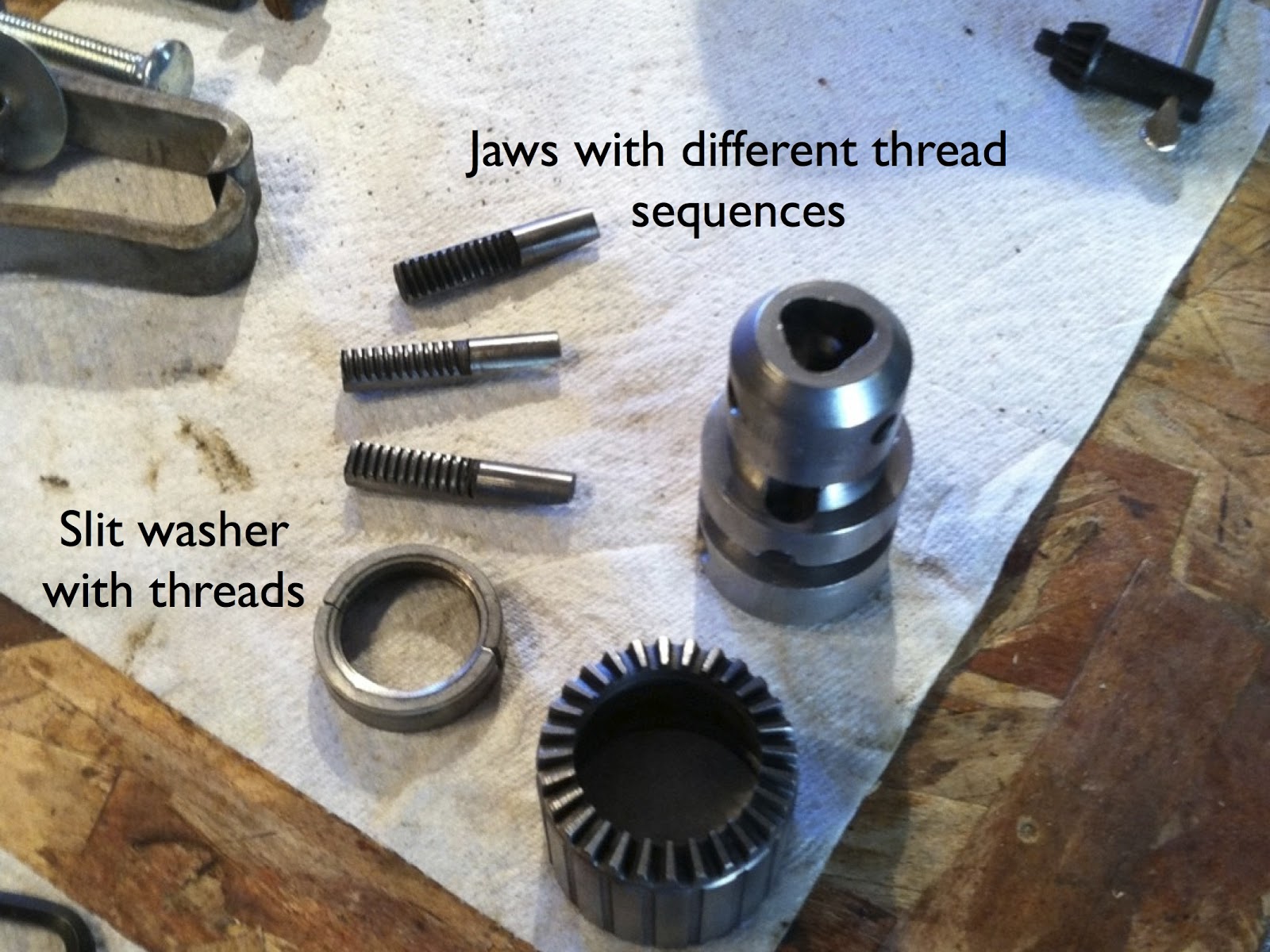
It turns out that the three jaws which go in and out of the Chuck and clamp down on the drill bit are not identical.  They each have grooves or threads which are different...and they are assembled inside the chuck in a very specific sequence.  A split washer is what rotates and moves the jaws up and down, or in and out if you happen to swing that way.

The procedure recommended marking the jaws and the housing before they are removed so that they can be put back together in that same sequence.  I used a marking pen to do just that....and in my cleverness, I managed to remove all markings during the cleaning and polishing process.  Great.  Good job Dan.  Now what?

In looking closely at the jaws, the grooves are designed as a beginning, middle and end creating a thread sequence.  The core housing, as it so happens, was also stamped with a “1, 2, and 3” in a clockwise direction (A dead give-away).


Logic says that if I aligned the three jaws in the correct sequence, it should work.  I reassembled the unit according to MICKYD’s procedure, greased up the jaws, and placed them in what I believed to be the correct thread sequence...and voila!  They fit, the unit rotates properly, and the jaws even go in and out.  Amazing.


After 20 years of separation, Rusty and Chuck were re-united....not a dry eye in the room.  The Chuck can now be used for drilling, and a variety of woodworking and mechanical projects.

Rusty and Chuck...Together Again


We even took time off to go camping...roast some marshmallows, and be together...just me and the boys.


The next Shopsmith Episode #8: Rusty finally begins reassembly...or will he?

Monday, September 24, 2012

Shopsmith Episode 6: Embracing the Bottom and other Misc Ramblings


A little side trip to the pedigree and history of Rusty...at least as much as we know.  The label shows it as a model 10ER (which stands for Experimental Revised).  I am not sure what the “10” means.  It has a serial number of 84353.

The best we can recollect, my father-in-law bought Rusty from a fellow Scout Master in the early ‘60s while he was living in Pomona, CA. He later moved to Calimesa, CA where Rusty found a new home in the dreaded garage attached to the yellow house (see my blog part 1: Prolog).

 I suspect that I am the third proud owner.

The Shopsmith was first developed by a Dr. Hans Goldschmidt in 1946, and began manufacturing by Magna Engineering in 1947.  The first units produced were nearly identical to Hans's original experimental model (hence the "E" model) and were sold through Montgomery Ward (honk if you remember Montgomery Ward).  There were around 200,000 of these units built during this era.  

The Original Shopsmith

Over the years, the Shopsmith has experienced a series of refinements and upgrades, beginning with the 10E, then later revised (hence 10ER).  Starting in the late fifties, the “Mark” series was introduced where the motor and pulley are hidden within a casing.  There have been many iterations in between.  

The Shopsmith Today:  Mark 7

The database of machines found on the Shopsmith 10ER users group web site places Rusty’s manufacturing date around late 1952 or early 1953.  Since it has an original speed changer and a Magna 4” jointer, which the first models did not have, these dates would be a good guess.


...and now, back to our regular programming...


Staying with the Middle

Let’s be honest....the Headstock unit is where all the fun is.  
It has rotating parts, shafts that go in and out, not one but TWO locking levers, and even an On/Off switch which gives you complete power over all things Shopsmith. If this was an attraction at Disneyland, the Headstock would be Fantasyland...a bunch of attractions and excitement all squeezed into one small area.  

On the other hand...the Baseplate at the end would be like the rockets - kinda fun, but all it does is go up and down.  Definitely not worth an E ticket (knock your cane against your walker if you remember E tickets).  


The Headrest is like the McDonnell Douglas Rocket in Tomorrowland - interesting to look at, but it doesn’t actually DO anything.  (Sigh) I think I need to take a break and find some churros or popcorn.

Notice the similarity?

As unexciting as these other parts might be, the Baseplate and Headrest are important to the operation of the Shopsmith and **yawn** need to be cleaned too.  Some WD-40 and steel wool, polish and waxing, and these units clean up rather nicely.   The cylinder sections which slide on the Way Tubes need extra attention to get them shiny and smooth.


Embracing the Bottom

OK, I must admit...I have seen the light; I have been converted and am now a true believer; I must give up my previous ways and habits; forsake the parts in the middle (for a while anyway), and embrace the bottom.  I need to start working on the wood bench, bench ends, and the casters or else I will need sky hooks to hold up the middle parts.

When I first found rusty, the bench ends were mounted on 2x4’s, which in turn were sitting on a set of non-locking casters.  This made the machine sit at least four or five inches higher than it should be, and prevented the unit from locking into place. 

The bench before


My plan is to drop the whole unit down to its intended height and use retractable casters mounted on the outside of the unit.  This would open up the space underneath the bench for a future cabinet to store the various Shopsmith parts and accessories. 

I used redwood planks for the solid bench...but in retrospect, I am hoping that these are not too soft of wood and allow excessive vibration of the unit.  I then cleaned and sanded the metal bench ends and support brackets, and painted them a Rustoleum Hammered Black. I bought a set of retractable casters from Rockler.com which are perfect for what I wanted.


The Bench After

Rusty is now ready for some assembly work to add back the Baseplate, Headrest, and perhaps the Way Tubes and Headstock.  Working our way up!

Tuesday, September 18, 2012

Shopsmith Episode 5: Electrification of the Motor!


  • Fire Extinguisher:  Check
  • Haz Mat Suit:  Check
  • DEFCON Level raised to DEFCON 3:  Check
  • Warn So Cal Edison of a pending power surge:  Check


We are now ready to test the motor, which has not seen electricity in nearly two decades.  The motor needs a great deal of cleanup, and will probably need some paint.  Nevertheless, I wanted to test the motor to make sure it runs, and is worth all the trouble of cleaning and painting

The power cord was in very bad shape - between various splices that have been made, rodents using it for hors d’oeuvres, and time itself, the cord has become a dangerous weapon.  When I opened the cover to the motor terminals, I was surprised to find the power cord terminated on the inside of the motor terminal...meaning I had to disassemble the motor case to gain access to the power terminals.


Disassembling the motor case wasn’t too difficult as there were only four long screws holding the casing together, despite one which was stubborn and had to be cut off.


The power cord wires were soldered to the outer two lug screws on the terminal block.  I decided that there was a better way, so I cut off the power cord wires in the back, then added two new terminal nuts to the front of the terminal block, and wired a new power cord to these terminal points using spades. 


I added a ground lug (green wire) to the motor casing, which originally they did not believe in grounding such things.  

The black spliced and taped wires allow the new on/off switch to be in the circuit.  The original switch is long gone, as it apparently burned out, and was simply by-passed.   

So we are ready for the test.  To find out the outcome (drum roll please), I have provided the original video of the first test.  See for yourself:


In the event the video doesn't show or play properly, click on the following to re-route you to YouTube:   AO Smith Motor Test

Well, as you can tell, I lived to see another day, So Cal Edison didn’t have a clue what just happened, and the world has been safely reduced to DEFCON 5.  Now, if I can just figure out how to get out of this Haz Mat suit....